Articles
Technical
- LM555 Duty Cycle Calculator
- Cornet/ZP3 Controversy
- ChatGPT Description of Hagerman Clipper
- LM555 Duty Cycle Expansion
- Starved Pedal Circuit
- Choke Rectification Calculator
- AC128 Ge PNP SPICE Model
- Spice Models
- Eliminating Noise in Vinyl Playback Systems
- Phono Equalization
- Cartridge Loading
- Designing a Capacitive Charge Pump Power Supply
- Calculating Differential Impedance of Parallel PCB Traces Without a Ground Plane
- Antenna VSWR Compensator Circuit
- Nano-Notch: Innovative Tunable RF Notch Filter Design
- Family of Intrinsically Absorptive Electronic Filters
- Falcon: Tunable 30MHz to 90MHz Bandpass Filter
- Clarion: A Simple 2A3 Design Project
- Rip Your Vinyl to Bits With a USB Phonostage
- Why Not 16-bit No-OS No-Filter Conversion?
- Monogram: A Tube Phonostage for 78s
- FryKleaner: An Audio Burn-in Generator
- FryKleaner.wav
- SeaModem: Transoceanic Communications Module
- On Reference RIAA Networks
- Calculating Optimum Snubbers
- Modified T-Coil Network
- A Look at Video Amplifier Peaking Networks
- Some Notes on Aperture Correction
- Optimum Spot Size for Raster-Scanned Monochrome CRT Displays
- SPICE Model Formulas
- Video Risetime Requirements for Computer-Driven Raster-Scan CRT Displays
- Video Amplifier Performance Criteria for High Resolution Displays
Design Ideas
- Crossfeed Network for Amplifier Input
- Two Transistor Circuit Replaces IC
- Analog Circuit is Accurate Battery Fuel Gauge
- Simple Circuit Safely Deep-Discharges NiCd Battery
- Power OK LED for PC
- Pi Filter has Sharp Notch
- Bi-Color LED Indicates Power/Fault
- Bi-Directional Level Translator
- Variable Low Pass Filter
- Base Current Compensated High Voltage Amplifier
- Model NTC Thermistor in SPICE
- Variable Length 22AWG Twisted Pair Transmission Line SPICE Model
- Improved Vbe Doubler
- Fan Speed Controller
Patents
- Thermal Fuse Breaker for Smart Socket [#62/752,837]
- Family of Intrisically Absorptive Electronic Filters
- Digital Drive of 3HMS
- Fan Blade Construction of 3HMS
- Hyperbolic Horn Helical Mass Spectrometer (3HMS) [#7,388,196]
- Method and Apparatus for Measuring Illumination Uniformity of a Liquid Crystal Light Valve Projector [#5,793,441]
- Bias Drive and Noise Reduction in Image Projectors [#5,471,255]
- Dynamic Gamma Correction Circuit for use in Image Projectors [#5,461,430]
Awards
- Trumpet Reference Stereophile Recommended Component 2014
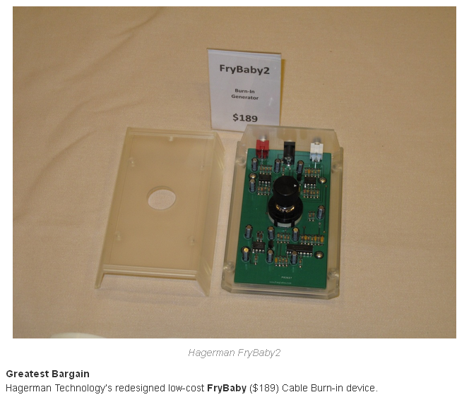
- FryBaby2 Greatest Bargain Award RMAF 2014
- The Third Annual Positive Feedback Online's Writers' Choice Awards 2006 [FryBaby]
- EnjoyTheMusic Blue Note Award 2005 [UFO]
- ECN/Xilinx Design Engineering Achievement Awards 1996
- Apex Microtechnology PB50/PB58 Design Contest 1992
- Motorola TMOS Design Idea Contest 1985
![EnjoyTheMusic Blue Note Award 2005 [UFO]](https://www.hagtech.com/images/bluenoteaward.jpg)
Videos
Discontinued Products
- Tuba EL84 Headphone amplifier
- Trumpet Reference - Vacuum Tube Phonostage
- FryCorder - Power Cord Burn-In Generator
- FryKleaner - Professional Burn-In Generator
- VacuTrace - Vacuum Tube Curve Tracer
- FryBaby - Portable Burn-In Generator
- Cornet2 - Vacuum Tube Phono
- Clarinet - Vacuum Tube Linestage
- HagClock - Low Noise Oscillator
- Bugle - Phono
- Power Supply - for Bugle Phono
- HagUsb - USB to SPDIF Converter
- Cymbal - 6H30 8 Watt Monoblock Amp
- Chime - Vacuum Tube USB DAC
- HagDac - Digital to Analog Converter
- The Ripper - Phono with USB Output
- Archiver - Variable EQ Phono with USB
- Cornet - Vacuum Tube Phono
- Bugle Pro - Variable EQ Phono
- Oboe Pro - Preamplifier
- FryDaddy - Cable Burn-In Generator
- Flugelhorn - Variable EQ Phono
- Step-Up - Transformer
- HA-10 - Vacuum Tube Headphone Amp
- DA-10 - Vacuum Tube USB DAC
- PA-10 - 2A3 6 Watt Monoblock Amp
- Violin - Tube Phono
- Euphonia - Phono
Blogs
Trumpet Reference
Cornet
FryBaby
Piccolo
HagUsb
Chime USB DAC
Cymbal Power Amp, Clarinet Linestage, Cornet Phonostage
UFO StrobeClamp
Trumpet Vacuum Tube Phono Stage
Jim Hagerman, Mar/02
This is one odd looking amplifier! Why did you ever make it such an ungainly shape? Were you just trying to be high-end cool?
This was not an exercise in trying to find something different for the sake of marketing. Yes, I wanted my product to have some personality and identity, but certainly not at the expense of sound. What happened here was the result of a study into power supply / amplifier interactions. I didn't like the common side-by-side approach in most gear. The stray magnetic and electrical fields are asymmetric about the channels and external interconnects. I didn't like the unbalance of the fields which would favor one of the channels. You also have to be aware of how a customer's interconnects and power cords will drape out of the rear of an amplifier. Is the power cord right next to an audio signal (I'm amazed at how much this happens)? Where will the power transformer sit in relation to the input tubes or turntable and cartridge? These are all aspects of design that I take into consideration.
The usual answer is a two-box approach. That is, a separate power supply. This can work just fine, but it also tends to break up the "star" ground at the input. It is also more expensive. Alas, engineering is the art of compromise. There are many solutions and each designer attempts to achieve their own goals in their own fashion. Wanting to keep the price down, I chose a single-box topology. The best way to accomplish this was with an over-and-under concept where the power supply was mounted under the amplifier. They are kept as far apart as possible with several layers of shielding between. Functionally, it's very much the same as separate, but stacked, boxes. Hey, why pay for the extra chassis?
You'll notice that the shape is that of a golden section. This is to minimize structural vibration colorations. Don't quote me, but I've heard or read that the golden ratio (1:0.618) is an optimum design for mechanical resonances, as is a sphere. The width/height is built to the golden ratio. So are the circuit boards inside. Anyhow, that's why the Trumpet looks the way it does; golden ratios with a power supply mounted symmetrically underneath the amplifier separated as far as the chassis will allow.
Ok, fine. But why wood?
This is not just any wood. It is hard white maple, a very strong hardwood with a very fine and non-porous grain. At first glance, it appears that the wooden front and rear panels are just for show. But that's just part of the story. They also provide mechanical damping to the aluminum chassis. Tap anywhere on this chassis and all you'll hear is a dull thud. No ping. No ringing.
What else do you do to minimize acoustic feedback and mechanical vibrations
The chassis is built like a suspension bridge. The front and rear panels act like rigid support towers. In between the high-grade fiberglass circuit boards are hung. The amplifier board has no center supports and is free to flex, the fiberglass being naturally self-damped. Under the support towers are sorbothane feet which provide a high level of cushion and decoupling from the mounting surface. Inside the black anodized aluminum cover are strategically placed rubber strips to keep the panels from acting like cymbals. It is also securely fastened to the front and rear towers via an army of screws. Tubes wear o-rings to reduce acoustic energy on the glass. Everything is designed to work in unison to provide minimal microphonic distortions. This is not your average steel box.
How do you handle grounding and shielding?
The first thing you see with the cover off is a remarkable lack of wires. The Trumpet does not look like any other audio product. Often you'll see a mass of wires routed all over the chassis. I am just appalled at some of the equipment I see out there with signal and power wires criss-crossing all over the place between controls, boards, and connectors. A virtual smorgasbord for unwanted coupling and interference, not to mention a completely haphazard grounding scheme.
The Trumpet's rear aluminum panel acts as the "star" ground and reference for all other signals. This is where the input and output connectors are, the turntable ground, and the Earth ground connection from the power cord. From this single low impedance plane, the ground spreads through the chassis. There are no loops (that was not easy). The circuit boards use full ground planes. But note, the signal and power grounding maintains a "star" configuration by judicious control of currents. Hey, it's not where the metal is, it's where the electrons are flowing. Not only do the signals on the circuit boards have solid reference points, but the ground planes also act as electric field shields. Even the power cord is specially double-shielded.
This product is very heavy, and it's not because of the chassis. Why is that?
I use a huge amount of iron in the power supply. That is, big transformers and chokes. This is no ordinary power supply. Not only is it choke filtered, but it is balanced too. Yes, I use both B+ and B- supply rails. The preamplifier runs off +/-300V supplies. But first, I want to point out that these are not simply choke filtered. They are choke regulated. Most supplies are designed where the rectifiers charge up capacitors 120 times a second. In the Trumpet, the rectifiers charge up inductors instead. There is a big difference between these two types of input filters. A properly designed inductive input will maintain a continuous ac mains current. This is in contrast to the large short duration current spikes (dozens of peak amps) observed in most equipment. Ever wondered where power line "buzz" came from?
To reduce supply ripple down into the uV range (starting at 350V), additional LC and RC filter stages are added. Active regulation is not used. Each high voltage rail gets smoothed by a total of LCLCRCRC filters. Component values are not just pulled out of a hat. These are very carefully designed sections that work hand-in-hand with the load. Inductor values are determined by the minimum load current theory. Capacitor values must be carefully chosen to react with the series equivalent resistance of the chokes for proper damping. Yes, an LC filter is a nice low pass filter, but if undamped will lead to ringing. Therefore, the capacitors must be correctly sized. The Trumpet supplies are set to be slightly overdamped (closer to Bessel than Butterworth). This prevents power line spikes from stimulating ringing in the filters. It also helps that the preamplifier acts as a constant-current type load.
In a bold innovative move, I also made the heater supply choke regulated. As far as I know, nobody else is doing it. This is a great trick which I believe will be copied by many. By simply running the 5V and 6.3V secondary windings in series, a full-wave rectified choke type input filter provides a decent dc output voltage without any of the huge ac current spike getting yanked down the power cord. Again, carefully designing an LCRC filter for no resonance, I got a dc output voltage with less than 5mV ripple. A side benefit is the most gentle heater turn on in the industry. This is important for long tube life and product reliability.
So that's why it's heavy. Lots of iron to smooth out the supplies and prevent ac mains current spikes. Unfortunately, it is also very expensive.
You mentioned the load is constant current. Does that imply class A operation?
Yes it does, and more. The circuits are fully balanced. Differential throughout. As such, each stage draws a constant current from the supplies regardless of signal. Differential circuits also reject common mode noise from the supplies or other unwanted external influences. The constant current load is almost like shunt regulation for the supply filters. They maintain low voltage ripple under load. I even pulled a small trick whereas even if the line voltage changes (wanders up and down), the bias of the tubes remains constant. That is, perfect first order power supply noise rejection. But this works only down to about 1Hz which I feel is good enough for audio.
Balanced amplification also allowed me to add the polarity controls. With both positive and negative going signals, you can pick which one to use to correct for system or source irregularities. Differential amplifier stages are just plain a better topology. The only drawback is you double the number of tubes and increase cost.
What about output drive? Can you handle long interconnects?
Yes. The output buffers are low impedance cathode followers loaded with constant current sources. It is important to note that all this is done with tubes. There are no semiconductors anywhere in the signal path. I don't cheat with FETs in the front-end.
What about your choice of components?
Premium quality parts are used throughout. The RCA jacks are gold plated, so are the sockets. All signal capacitors are audiophile-grade polypropylene types, supplies are bypassed with film capacitors, resistors are power metal films, and power supply diodes are soft-recovery types. Even the mute switches use expensive low-current gold contacts.
Michael Fremer, Stereophile Dec/02
Built in Hawaii, the Hagerman Technology Trumpet is a well-built if quirky, all-tube phono preamp available in single-ended and balanced-output editions. Check out the website, www.hagtech.com; Jim Hagerman's resume and accomplishments will assure you that you are not buying some garage tinkerer's design. You'll also find some impressive design and build details, especially given the Trumpet's reasonable price of $1895.
I opted for the single-ended (the design itself is balanced), which has 44dB of gain (vs 50dB balanced). This meant I was unable to use low-output MCs with the Trumpet, though it had almost enough gain for the Lyra Titan's 0.45mV output into the Hovland HP-100's relatively low-gain line stage.
The Trumpet uses hand-matched quartets of 12AX7 and 12AU7 tubes, but Hagerman encourages NOS or other exact substitutes, as long as youu use carefully matched sets (because of the balanced operation). To operate, you first turn on the heaters, wait a minute, then turn on the high-voltage section. Then you go from Mute to positive or inverted polarity. (Yes - an $1895 all-tube phono stage with a polarity switch.) You can solder in loading resistors of your choice.
I used the Rega Exact and Adcom Crosscoil cartridges. The HT Trumpet proved competitive in direct comparison with the Lamm Deluxe, with an open, airy, detailed, and thoroughly intoxicating sound. Still, specs-wise, the Trumpet's 66dB [actually 74dBA] signal/noise ratio couldn't match the Lamm's 86dB in MM mode, and its 750 ohm output impedance means you'd better keep your interconnects very short and low in capacitance.
The Trumpet's bass was very well-controlled, texturally coherent, and exceptionally nimble, given the Exact's less-than-controlled bass, and the pacing and rythmic flow were stellar. In short, the HT Trumpet sounded stunning, and was a total pleasure to listen to - which is what I did for many hours. Dynamic slam was somewhat diminished compared to the Lamm LP2's, but not to any great degree. The results were ear-opening, the HT's rich sound complementing the somewhat dry but well-controlled Adcom.
The Lamm LP2 is a tubed MM design with a transformer in front for MC, so you could add a $5000 Audio Note transformer to the Hagerman Trumpet and still spend less than $7000. Or you could buy some far less expensive transformers and do it yourself, and the results could be incredible for under $3000. I'll have more to say about the Trumpet with transformer as soon as possible.
Manufacturer's Response:
Thank you, Mr. Fremer; your writing is clear and concise, accurately articulating the sonic qualities of my Trumpet phono stage - no easy task when space and time are limited. I totally agree with your comments of "open, airy, detailed, and thoroughly intoxicating sound" and "pacing and rythmic flow were stellar." To me, it is this toe-tapping, head-nodding, get-up-and-dance quality that really makes the Trumpet swing.
Quirky? Indeed, the Trumpet is an odd-looking, perhaps even strangely beautiful machine. Its tall chassis is built to minimize microphonics, interconnections (only one internal cable), and ground loops. The no-frills design emphasizes components of exceptional quality, implementing an expensive balanced circuit topology (double the number of tubes) and choke regulated supplies.
Regarding signal-to-noise, there are various methods to specify and measure this parameter, so it is easy to compare apples and oranges. For example, the extraordinary 86dB quoted for the Lamm LP2 is valid only with a 13mV cartridge. Is that relevant? Similarly, John Atkinson recently clocked a $29,000 phono stage at 58dB. But was it objectionable? It is easy to get caught up in a numbers race, and I fully understand why some manufacturers leave out the details and just say "low noise, high gain." The most important consideration is sound. Is the noise audible or intrusive under listening conditions?
For the record, I believe the best way to specify SNR is using A-weighted dBu. This is input-referred noise voltage relative to 1mW output (0.775V RMS into 600 ohms), and takes into account bothe gain and human audibility. The Trumpet achieves a respectable -110dBu, an equivalent input noise voltage of 2.5uV.
I do not consider a 750 ohm output impedance to be worrisome. It is remarkably low for an all-tube amplifier, and almost five times better than the LP2. It is, in fact, low enough to drive ten meters of typical interconnect past 200kHz, which the Trumpet's wide-bandwidth design is perfectly capable of accommodating.
Yes, the Trumpet is not well suited to cartridges under 1mV, adn an external step-up transformer is recommended. Not only does the transformer supply virtually noise-free gain, it also provides matched impedance loading for the cartridge.
Thanks again to Mr. Fremer and Stereophile for an informative article and for continuing to carry the torch for analog and vinyl!
Bugle Phono
Michael Fremer, Stereophile Aug/03
Hagerman Technology Bugle: For $125, Hagerman Technology sells the Bugle, a battery-powered phono section that's ridiculously good for the money. You can even buy it as a "half-kit" circuit board with pans, for $25; for another $25 you can buy the parts from DigiKey. You can play with various op-amps (they mount on plug-in sockets) and resistor brands - all of which, of course, sound different. There's a place to solder in loading resistors of your choice. Because the Bugle uses a split, passive RC-type equalization network, it's easy to optimize it for alternative EQ curves such as pre-1955 LPs or 78s. Hagerman calls this AnyEQ; you'll find everything you'll need to calculate resistor values for various curves at www.hagtech.com/equalization.html.
The Bugle can be built with 40, 50, or 60dB of gain (mine was configured for 60dB), but there's one drawback: the estimated life of the two 9V alkaline batteries is around 16 hours (there's an On/Off switch). However, a new plug-in power supply option ($25, half-kit only) solves that. And the Bugle comes with a 30-day money-back guarantee. You can't go wrong.
The Bugle sounded very quiet, surprisingly somewhat warm yet reasonably detailed, and a bit woolly. I ran the $4500 Lyra Titan (as well as more appropriately priced cartridges) into it, and you know what? It wasn't bad! Images lacked pinpoint specificity, and transients were a bit softened, but for $125 - or more than twice that - the Bugle was quite a credible performer.
Also on Hagerman's website was a new $895 transformer-based step-up (12, 18, or 24dB gain) that makes the superb-sounding all-tube Trumpet ($1895, reviewed in the December 2002 "Analog Corner") friendly to MC cartridges. I tried the Trumpet with a very expensive Audio Tekne transformer, and the results were Class A. Hagerman's own combo of transformer and Trumpet, for $2790, should be a sweet performer.
iRIAA Filter
Michael Fremer, Stereophile Oct/01
Don't want to spend $350? How about $29 or $39 [now $50]? Hagerman Technology (www.hagtech.com) will sell you their RIAA Filter, built or in kit form [kit available from Old Colony Sound Labs]. It will perform the inverse RIAA function and drop line-level signals by 40 or 60dB, depending on the output set you choose. Inputs are for 50 or 600 ohm sources. Frequency response is claimed to be accurate to within +/-0.25dB from 10Hz to 100kHz, and the network includes a "correctly placed upper 3.18us corner (50kHz) in it's transfer function," according to designer Jim Hagerman.
This ultrasonic rolloff has to do with the response of the RIAA curve, which, on the LP cutting side, rolls off the bass and boosts the highs. If the boost were allowed to continue on to infinity, the result might be burnt-out cutter heads because no amplifier has unlimited gain. According to Hagerman [ok, I got it from Allen Wright], the manual for the Neumann cutting head specifies the 3.18us corner, so he includes it; the "inverse" RIAA curve is essentially what the cutter head is fed. He also claims that the RIAA network in your preamp (which applies the opposite EQ, of course) should take the corner into account, but that most don't - a subject to be explored at another time. Meanwhile, check out the www.hagtech.com - there's interesting stuff there.
VacuTrace
John Atwood, Vacuum Tube Valley #16 (2001)
The characteristic curves of a vacuum tube, such as those seen in tube databooks, can provide nearly all the behavior of a tube needed to design a circuit. The curves can also show the defects, such as nonlinearity, that are difficult to discover with conventional tube testers. Where matched-tubes are needed, matching curves ensure a good match over all operating conditions. The benefits of curve tracing are further explained in my article, "Screening Vacuum Tubes," in issue #1 of VTV, page 9.
The main problem in curve-tracing vacuum tubes is the lack of affordable tracers. The Tektronix 570 curve tracer is very rare, and sells for thousands of dollars, if available at all. Audiomatica (Italy) made a good computer-controlled curve tracer, but it cost $4000, and is no longer available. Now Hagerman Technology has brought out the "VacuTrace," which connects to a conventional oscilloscope, for only $999. It is fully analog and generates a display nearly identical to that of a Tektronix 570. In addition to the trace capability, there is a 3.5 digit digital meter that displays operating voltages, transconductance (gm), and output conductance (gp), equal to 1/rp). Mu can be easily calculated from the equation mu = gm/gp. An analog tracer of this type does not have the storage and printout of computer-controlled types, but at its price, it offers a lot of capabilities.
The VacuTrace comes with a set of adapter boards that allow testing of: pairs of 6L6-pinout tubes (covering most audio power tubes), octal and noval dual triodes (e.g. 6SN7GT and 12AU7/6DJ8), power tubes (5V rectifier and a single 2A3/300B triode), and a blank board with two octal and two noval sockets for accommodating other types. It also comes with a power cord and three BNC-to-BNC coaxial cables for the oscilloscope connection.
The oscilloscope needed for displaying the curves must run in its "X-Y" mode with a sensitivity down to 0.1/division. There is a Z-axis (intensity) connection which is used to create dotted lines in the A/B comparison mode. It is rated as a "TTL signal level" (0-5V), which is the standard on modern solid-state scopes. It was found that this signal also worked on older scopes that provide access to the CRT cathode. The high-frequency requirements are modest and should be accommodated by virtually any scope. However, DC-coupled vertical and horizontal amplifiers should be used, thus ruling out the old AC-coupled TV serviceman's scopes.
The VacuTrace itself is solidly built with wood side-panels and a rugged powder-coated panel. The controls are clearly marked; however, some serve dual purposes, depending on whether curve-tracing or meter measurements are being done. There are no calibration marks on the front panel - you must make sure your oscilloscope is accurately calibrated, since it is the only indicator of currents or voltages in the curve tracer mode. In the measurement mode, the digital panel meter is used to accurately set the operating conditions. The design is conservative - a pair of 6L6 were left tracing at full power all night and the cabinet was only mildly warm the next day.
The 29-page user's manual is professionally laid-out and clearly covers set-up and operation. It assumes, however, you know how to interpret the curves. Nearly half the manual contains the full set of schematics, unusual for equipment of this complexity and cost. Examination of the schematic shows clever analog circuit design and plenty of protection circuits. Going to www.hagtech.com gives even more information, including a comprehensive and honest FAQ (Frequently Asked Questions).
For purposes of comparison, the Tek 570 is rated a 0 to 500V @ 1A for its plate supply, has up to 13 grid steps, and has many more operating modes. However, its accuracy id 3% for the voltages and 3% for its display. Thus the VacuTrace is a somewhat more modest tester than the 570, although a bit more accurate. The accuracy of the scope used with the VacuTrace needs to be accounted for, though. A limit of 380V and 200mA will not push power tubes throughout the full range they operate at within an amp. However, it is enough to generate valid curves for the purposes of design and matching.
In the "normal" mode, two tubes can be swept at the same time. There is a 20 ohm resistor in the cathode of each tube which is used to measure the current through the tube. To measure high currents (up to 200mA), the VacuTrace can be switched into its "2A" mode, where the two resistors are paralleled, giving 10 ohms, and doubling the vertical current scale. One tube can be swept at a time in this mode. For pentodes, cathode current is not really the same as plate current, since the screen current is included. This does not seriously compromise measurements, especially in the operating regions where tubes are used for audio amplifiers. The cathode resistor causes a small amount of degeneration, which only becomes noticeable when sweeping the transfer function curves for high power tubes.
When testing tubes, it is important to be able to limit the voltage and power applied to the tube, both to protect the tube, and to protect the tester in case a short-circuit develops in the tube. In addition to front-panel controls that vary the voltage and current to the tube, the VacuTrace is unique in having a power limit control. When displaying a set of curves, if the power limit is cranked down, a nice hyperbolic divot is taken out of the curves, showing that it is correctly calculating the maximum permissible power at all points of the curve. A downside of these limiting circuits is that it is not always obvious when they are coming into play, so you often find you need to twiddle all three controls to make sure you are getting the reading you expect.
A yellow "caution" LED lights up when high voltages are present at the tube sockets. However, the base of the sockets are exposed, and if you try, you can touch high voltages. As a result, this should not be used around children or irresponsible people. It is hard to get shocked without trying, but the danger is still present.
The most commonly-used curves are the plate characteristic curves, which plot plate current vs plate voltage for a series of negative grid steps, starting at 0 volts. An example of these curves for an old General Electric 6L6G in pentode mode is shown in fig. 1. For comparison, the same tube pentode mode using the Tek 570 curve tracer is shown in fig. 2. The main difference between the curves is at low plate voltage and at low plate current. The minimum plate voltage for the VacuTrace stops at about 8 volts, at idle, but goes to zero while sweeping. The slight dip in the lower left corner of the 570 curves shows the effect of increasing screen current robbing some of the plate current.
In the VacuTrace curves, these dips don't show up, because the cathode current (which includes the screen current) is what is being measured. The behaviour of pentodes is more accurately reflected in the 570 curves. The oscilloscope used with the VacuTrace for these tests was a Tektronix 502 in its X-Y mode.
Hooking a scope and DVM up to the pins of the tube begin traced showed that the applied voltages closely matched their specs. The built-in DVM was quite accurate - better than 0.4%. The screen voltage is regulated to within 2 volts. The filament supply is unregulated, and runs a little high. With no tube plugged in, the filament voltage was 6.95Vrms, with a single 6550, the voltage dropped to 6.70Vrms, and with two 6550s, the voltage was 6.50Vrms. All voltages were measured with a lines voltage of exactly 120V. The lack of regulation can make repeatable measurements difficult if there are voltage changes. If this is a problem, use a Sola or other ferro-resonant regulating transformer in the power line.
While testing the accuracy of the VacuTrace, some discrepancies were noted in the display, visible as the plate current differences between Tek 570 and VacuTrace curves of the 6L6G. Doing some accurate measurements showed that the cathode current was 12.5mA/division, not the 10mA/division stated in the manual. Similarly, the grid voltage was actually 10V/div, not the 12.5V/div specified in the manual. Checking in with Jim Hagerman confirmed that there was an error in deriving the cathode current and grid voltage specs from the actual design. All new manuals will have the correct readings specified.
For a complex instrument like the VacuTrace, there are many parameters and features to consider when considering a purchase. Some of the important pros and cons I've discovered should help you make a decision.
First the cons:
- The maximum plate voltage and current are a bit limited.
- Cathode current, not plate current, is measured.
- Unregulated filament voltage.
- Only common audio tubes testable without making custom adapter boards.
- Needs a decent oscilloscope.
Now the pros:
- The accuracy of the instrument is good.
- Well-designed and "bullet-proof."
- Built-in meter facilitates measuring and matching tubes.
- Handy A-B comparison mode.
- Tube curves can often be very revealing.
- The price is very good for what you get.
On the whole, I would recommend the VacuTrace for those who are seriously into testing their tubes, musical instrument, or hi-fi repair shops that need to accurately match tubes, or tube dealers that want to give their tubes a good screening. The only [;aces I would not recommend it would be standards labs or other places where the utmost in performance is needed. Otherwise, it gives excellent value for the money, and allows far more detailed measurements than available with conventional tube testers or tube matchers.
Charles Hansen, audioXpress Feb/02
The VacuTrace performs measurements of both static and dynamic vacuum-tube characteristics under simulated operating conditions. A plate-supply amplifier and grid-step generator produce voltages that are applied to the device under test (DUT). The effects of these signals on the DUT produce a family of characteristic curves, which are then displayed on an analog oscilloscope (which must have X-Y and preferably Z-axis inputs).
The VacuTrace generates characteristic curves for a number of triode, pentode, and rectifier tubes. It can also display the matching on any two tubes, or the halves of dual triodes. The curves can sweep to 400V plate voltage, -70V grid voltage, 300V screen voltage, with up to 200mA cathode current and 20W plate dissipation. In addition, the VacuTrace provides digital readouts of a number of paramters.
The front panel (Photo 1) shows a 6SN7 plugged into one of the four socket adapter cards that connect (one at a time) to the top of the tester, and are held in place with wing nuts. Each adapter card has a rectangular 14-pin male Molex-style connector that mates with a female connector on top of the VacuTrace. Component pins, which project through the bottom the of adapter cards, are sharp [now I trim them], so you need to handle the board with care.
The rectangular display just below the installed adapters card is the digital readout for the voltages, current, transconductance, and transadmittance. The LED at the left of the display is the status light, which is red in standby mode, green during normal operation, and flashes yellow if there is an overload. The yellow caution LED at the right of the display lights when more than 70V is present at the test connector. Themiddle and lower rows of the unit are described in Table 1.
Adapter Card Descriptions
- Dual triodes adapter, with a 9A 9-pin "12AX7/6DJ8" and 8BD octal "6SN7" sockets and a slide switch labeled "6.3V" and "12.6V" to select filament connections. The actual voltage is always 6.3V, so 12.6V tubes suchas the 12AX7 have their filaments connected in parallel.
- Power pentodes adapter, with two 7AC octal "6L6" (6V6, 6L6, KT66, KT88, KT90, 5881, 6550) sockets. There is a wire jumper from pin 1 to pin 8 on this card that gives it the capability to test the 8EP octale socket 6CA7/EL34, which has a separate suppressor grid connection.
- Power triode and diode adapter, with a 4D 4-pin socket for "2A3" or "300B", selected by the left slide switch. The octal 5T "5Y3" (5U4) socket also has a slide switch [since removed], labeled "P4" and "P6", to choose which plate (pin 4 or 6) is operating. I assume you can also test the 5DA socket GZ34/5AR4 tube with its heater-cathode.
- Blank socket adapter, with circuit board patterns for two octal and two 9-pin miniature sockets. You interconnect the sockets to the 14-pin rectangular connector with jumper wires.
There are no provisions for 7-pin tubes, given all the variations on pinouts [see my new jumper card]. There is no standard board for 9-pin miniature pentodes, but there is an example on page 15-16 of the manual showing the blank board configure for a 6BQ5/EL84 and 6267/EF86. I did not attempt to customize the blank board, so my 6AV6 and the EL84s that Ed Dell sent me went unused.
The rear panel (Photo 3) holds the IEC AC power connector with integral fuse holder, power switch, and three BNC jacks for connecting the VacuTrace output signals to an analog oscilloscope.
A kit version of the VacuTrace is also available [no longer]. Photo 4 shows the interior view. The chassis is in two halves, with the upper section fitting into a lower sub-assembly consisting of the wood side panels and an aluminum bottom plate. The electronics are contained on one large epoxy PC board, with a Hammond 370FX transformer mounted to the chassis. A cutout in the PC board fits around the transformer. All connections to the front and rear panel controls are by means os flat flex cable addemblies.
The component density is quite high on the PC board. I didn't see any surface-mount parts, but the resistors and caps are about as small as they get in through-lead parts. Three MOSFETs and a linear regulator IC are mounted on PC board heatsinks. This is really a professional circuit board design!
The 30-page User's Guide is excellent, with a full nine-page set of schematics. The explanations are brief and well-written, and each function is covered in just the right detail. I was able to test all the vacuum tubes I had on hand after only a brief familiarization with the VacuTrace controls.
I designed a similar Curve Tracer Adapter device for semiconductors, and there are some similarities to the VacuTrace. Both require an analog oscilloscope, with at least X-Y input capability. The VacuTrace deals with only one polarity for tube tests. A transistor curve tracer's collector/drain supply must deal with N-channel as well as P-channel devices.
The VacuTrace grid-step generator needs to generate only negative polarity voltage steps. Bipolar transistors require base current steps of both polarities. FETs require gate voltage steps, and the polarity differes not only with N or P types, but also whether the device under test has a depletion mode or enhancement mode gate. A transistor curve tracer also supports testing of thyristors, IGBTs, unijunction transistors, and (without use of the base/gate generator) diodes and zeners.
This is not to portray the VacuTrace as a bare-bones test tool. It has the very useful digital readout, lots of internal protectio (for the tester - if you intentionally overload your tubes, that is your choice), plate and grid supplies for two tubes, and a Z-axis signal that lets you see the curves for these two tubes simultaneously. If your scope has a Z-axis (intensity) input, a 48kHz chopper modulates the B tube trace so it appears as a dotted line.
Also, my curve tracer just full-wave-rectified the 60Hz collector/drain supply transformer to simplify the sweep supply design. The VacuTrace uses power MOSFETs driven by a ramp generator to produce a higher- frequency triangle-shaped plate-voltage sweep for higher persistence and better definition at the sweep peaks.
Figure 1 shows a block diagram of the VacuTrace testing a triode-connected pentode. Voltages corresponding to the combined effects of the triangle plate voltage supply, the grid-step voltage generator, and the voltage across cathode-current sense resistor Rk are applied through op-amp attenuator/buffers to the oscilloscope X-axis (horizontal input), Y-axis (vertical input), and Z-axis via three BNC jacks located on the rear panel. The scope channels must be DC-coupled, but you don't need a wide bandwidth on any of the channels.
If using a single-channel scope, turn the time-base switch to the X or external position. A two-channel scope with an XY time-base switch position can use one channel as the X channel, and the other channel as the Y channel. Appropriate scaling factors (volts/current per division) are given in the User's Manual.
There are two ways to display curves: cathode current versus plate voltage (Fig. 1) and cathode current versus grid voltage. The waveforms for the plate-voltage amplifier, the grid-step voltage, and the resultant plate sweep curve scope display (Vp versus Ik) are also shown in Fig. 1. Note that the screen is driven from a separate MOSFET amplifier, which in pentode mode derives its adjustable supply from the plate voltage sweep. In triode mode, the screen grid is connected to the plate supply through the limiting resistor.
There are two filament voltage windings available: 5V AC and 6.3V AC. As mentioned previously, tubes such as the 12AX7 have their filaments connected in parallel across the 6.3V winding. A separate power supply is used to provide +/-6V DC for the opamps and other control circuits. The digital logic is CMOS, and it uses the +6V DC side of this bipolar supply.
The grid-step generator provides grid voltage, stepped in eight equal increments by a staircase, or step generator, on successive sweeps of the plate voltage. The first step has a value of zero. It then decreases at a rate of one step per cycle of the plate sweep (value selected by the grid steps switch) down to seven times that value, and then returns to zero after the eight steps are complete. The pattern repeats as long as the VacuTrace is in the sweep mode.
Cathode current through the DUT flows through the cathode resistor, and the voltage drop across it provides the vertical (Y-axis) signal. The sensitivity of the plate and grid voltages and cathode current is set by their respective controls. Note that the 20 ohm cathode-current sense resistor causes a bit of degeneration that introduces small errors in the sweep curves, since the actual grid-cathode voltage changes as a function of cathode current. VacuTrace subtracts out this error for Vg and gm measurements, but the error remains in the scope-displayed traces.
The cure for this would be another transformer, so the grid voltage could be floated between the grid and cathode. This would be a nonstandard transformer voltage; both expensive and space-consuming. (This extra supply is absolutely necessary for the base/gate supply in a transistor curve tracer, because the base current is a significant portion of the emitter current. In order to convey actual collector current, it must not flow through the emitter current-sensing resistor.)
In the hold mode, the sweep is disabled, and the Vp plate voltage remains at the preset limit setting displayed on the scope X-axis in sweep mode. The other fixed voltages and current (Vs, Vg, Ik) are easily measured by means of the VacuTrace's LED digital display. Grid voltage appears as a positive number in the display ("20" means -20Vg), and transconductance is displayed in mmhos, not the more common umhos given in the tube manuals.
In transconductance (gm) mode, a625 Hz modulation is added to the grid voltage. The dynamic peak-peak grid voltage and resulting AC component of the cathode-current modulation is used to calculate transconductance. Similarly, in transadmittance (gp) mode, the plate voltage is modulated and the dynamic cathode current is used to determine output conductance.
I had a number of tubes on hand to test the VacuTrace... The curves for 6L6 "A" (sample #1) are shown in Fig. 3. The curves for 6L6 "B" (sample #9) are shown in Fig. 4. As you can see, there is some "looping" during the retrace with decreasing B+ voltage. The looping is caused by two things.
In triode mode it is due to the bandwidth limitation of the grid amplifier. You can compensate for this by slowing down the repitition rate. The lower the peak plate voltage, the shorter the sweep and hence the faster the grid amplifier must recover. The grid amplifier is tuned for a step response and is rather insensitive to load capacitance.
The largest loop is seen when the grid must step from most negative to zero. This is where you see a small loop near zero plate voltage. As the plate ramp sweeps back down, the grid has settled and the curve is correct.
With pentodes there is an additional problem: the current drawn from the screen supply. The VacuTrace screen amplifier does not have a real low impedance and will droop a bit under heavy load. This causes pentode curves to split. Unlike the other looping problem, running a faster sweep rate will help cure this one.
Tube element capacitance and stray capacitance in the test fixture also allow some of the plate current to bypass the tube itself. Laboratory analog semiconductor curve tracers (such as the Tek 576 and 577) use elaborate capacitance cancellation circuitry that is beyond the scope (no pun intended) of the VacuTrace design, since each tube under test will have a different load. This is not a major problem. After minimizing looping as just described, the best approximation of the actual characteristic curve when looping is present is an imaginary straight line down the middle of the loop.
I have included the "A/B" trace for these two tubes in Fig. 5, even though the "B" trace is not blanked (see fix in Fig. 2 for the Tek 7603 scope). You can still differentiate between the two tube curves for matching purposes, so the VacuTrace is useful even for scopes without a Z-axis input capability. The VacuTrace shares a common plate supply when two tubes are used for comparison. It alternates between the two tubes by cycling each grid into cutoff.
Since there were good specifications for the triode-connected 6L6 in the tub manual, I ran sample #1 in triode mode. The curves are shown in Fig. 6. Next up were the IEC Mullard EL34s, which came in a singl box marked "lab-matched balanced pair." According to the scope traces (Figs. 7 and 8) for these two tubes, they weren't matched very well at all.
The 5Y3 curves so not use the grid step input. Figure 9 is the pin-6 plate curve in "A" mode, which shows a blur of curves [since fixed by tying the plates together]. Jim Hagerman explained that tracing diodes is more difficult because they tend to trigger the shutdown circuit so fast. they draw high current at low plate voltages, while the VacuTrace is best at delivering high current at high voltage (or low power dissipation in the plate supply), making it the most accurate with triodes.
As he suggested, things were better with the 5Y3 in "2A" mode, which doubles the current and power, providing plate current up to 200mA. Figure 10 shows the single 5Y3 trace with the voltage and current reduced, in "2A" mode.
The dual triode adapter has one octal and one 9-pin socket. You can use only one socket at a time. Selecting "A" or "B" switches between the two sections of the triode, while "A/B" shows both curve simultaneously.
The "A" section curves for the 6SN7 are shown in Fig. 11. The "B" curves were so close I couldn't see any appreciable difference in "A/B" mode. This close match is confirmed by the measured data for the two sections in Table 2.
My next triode test was with the JAN 5814A/12AU7 (Fig. 12). Again, the curves for the two sections were nearly identical. And loop how similar they are to the 6SN7 in Fig. 11.
Figure 13 gives the curves for the "A" section of the 12AX7, whose "B" section curves did show a noticeable difference (not shown). This is reflected in the wider spread of measured data in Table 2. I had to use the EXT/10 scope setting here to get the best display. the 0-250V DC plate sweep is now crammed into the first quarter of the horizontal display.
The plate resistances, rp, for the 6L6s in pentode mdoe (calculated from 1/gp) are about 50% high, while in triode mode they are very close to the specified value. The ADC in the display must cover a very large voltage range - 400V down to millivolts - and the gp signal for pentodes is less than 50mV. I did not run the EL34s as triodes, due to the lack of published gm, rp, and mu specs.
The performance of the VacuTrace as a curve tracer will be limited by the analog oscilloscope used for display, which I described with my particular cope, a Tek 7603. However, a comparison of the VacuTrace data with that of the Audiomatica Sofia (almost three times the cost) shows reasonably good correlation, especially for the triodes. Once set up, it is very easy to test multiple samples of the same tube type. In pentode mode I found that small variations in the operating point with both curve tracers could produce large paramter changes, especially in gm.
The VacuTrace is easy to use and a real value!
Manufacturer's Response:
I'd like to thank Mr. Hansen for his review of my VacuTrace. Producing such a detailed and thorough article requires much effort.
It might help to elaborate on a few points made in the article. Forst was the author's discovery that his "lab matched" tubes were actually not. This may happen more often than readers might expect. Single point matching can be inadequate. Personally, I believe the truest way to match tubes is the "overlapping curves" method used in the VacuTrace (or by other curve tracing techniques).
Mr. Hansen notes that measured tube parameters for pentodes are very sensitive to changes in operating point. This is indeed the case, since pentodes have very high gain and are quite nonlinear. You won't see many pentode output stages operating without feedback! It was also seen that the VacuTrace readings for rp (1/gp) were a bit on the high side. This might be caued by the fact that VacuTrace does not separate out the screen current.
Finally, diode curves were found to have an oscillation causing the displayed curve to be very wide. I discovered this to be due to the P4/P6 switch, which selects only one anode at a ti,e. Floating an anode does not make the tube happy. When both anodes were tied together, the displayed curve became very clean and thin. I will be removing this switch from future production.